$ cd /projects/chordkiller
ChordKiller — FPGA DAC From Scratch
Head-Fi diary: Project 100K+ Taps FPGA DAC
GitHub: TBD — considering open-sourcing (including Gerbers + BOM)
PRE — Idea · Setup · Build
Goal: Build a DAVE-class DAC for 1/25th the price. From zero FPGA
knowledge. In three months. Because how hard can it be?
The backstory starts in the 1980s. Music has been my lifeline for as
long as I can remember. As an autistic person, the ONLY way I can
concentrate and get things done — coding, thinking, existing — is
with headphones on my head. That's been true for 40 years.
The obsession with audio hardware predates this project by decades.
In 2002 I was on the Rockbox mailing list — an open-source
firmware project for the Archos Jukebox media player — debugging
gapless playback, analyzing CBR vs VBR decoding artifacts, and asking
about ID3 tag filtering before data hits the decoder chip. Hacking
audio player firmware at the hardware level, 23 years before building
my own DAC. The thread was always there.
Fast forward to Chord Mojo 1. When I first heard music through that
thing, something shifted. Details I'd never perceived before: the
squeaking of a piano bench. Someone coughing in the audience. The
texture of bows being pulled across cello strings. It wasn't "music
listening" anymore — it was "music perceiving." I remember sitting in
a client's office, Chord Mojo, Sennheiser IE800, Audirvana feeding
Olafur Arnalds in 96kHz. I could hear it all. And I loved it.
I tried other DACs. Bought an RME ADI-2 DAC in Japan alongside a
Hifiman HE1000 Unveiled. Great reviews, great specs. Back home...
I hated it. Flat. Boring. I tried every filter setting — linear
phase, NOS, minimum phase — but I couldn't articulate WHY it was
wrong. I just missed "falling into the depth of music." That feeling
where reverb creates a three-dimensional space and you're INSIDE it.
Last resort: plugged in my Mojo 2. Magic was back instantly.
Mojo 2 → Burson Soloist → Hifiman planars? Transcendent. That
confirmed it wasn't placebo. Something about Rob Watts' approach —
massive tap counts, noise shaping, transient precision — creates what
I can only describe as "auditory OLED." Pitch black background. Razor
sharp transients. High-contrast sound that makes music feel real.
So naturally: what's the best headphone? Hifiman Susvara. Bought it.
Loved it. But then... what's next? If Watts figured out that more
taps = more magic, then I need more taps. Hugo TT2? $5k. DAVE?
$12k+. No. I don't pay $12k for a DAC. I'd rather build my own.
Because: I've been writing software since age 6. Over 40 years. And
what's an FPGA? Software-defined hardware. "How hard can it be?"
Famous last words.
Starting from ZERO:
- Never touched Verilog in my life
- Never used an oscilloscope
- Never designed a circuit
- Never ordered a PCB
- Never heard of sigma-delta modulation
- Never implemented a FIR filter
Using AI as my teacher (Claude, specifically — learning the way
I learn best: try, fail, ask questions, remember forever),
I went into full hyperfocus mode and speedran the entire discipline.
10 weeks later: 229,376-tap polyphase FIR. 5th-order noise shaper.
Pulse array output. Custom 4-layer PCBs from China. Audio coming out
of an FPGA that sounds like it has no business sounding this good.
Format: FPGA audio DAC — digital signal processing in Verilog,
analog output stage on custom PCB, MATLAB for algorithm validation.
Stack:
- Xilinx Nexys Video (XC7A200T Artix-7, $500)
- Amanero Combo384 USB-to-I2S (all sample rates)
- Verilog (89 files, 28,018 lines)
- Vivado 2025.2 (synthesis + P&R on i9-14900K Gaming PC)
- MATLAB (fixed-point SDM modeling, NTF analysis)
- Python (coefficient generation, UART interface, captures)
- KiCad (custom PCB design, currently v0.4.3 — 4-layer board)
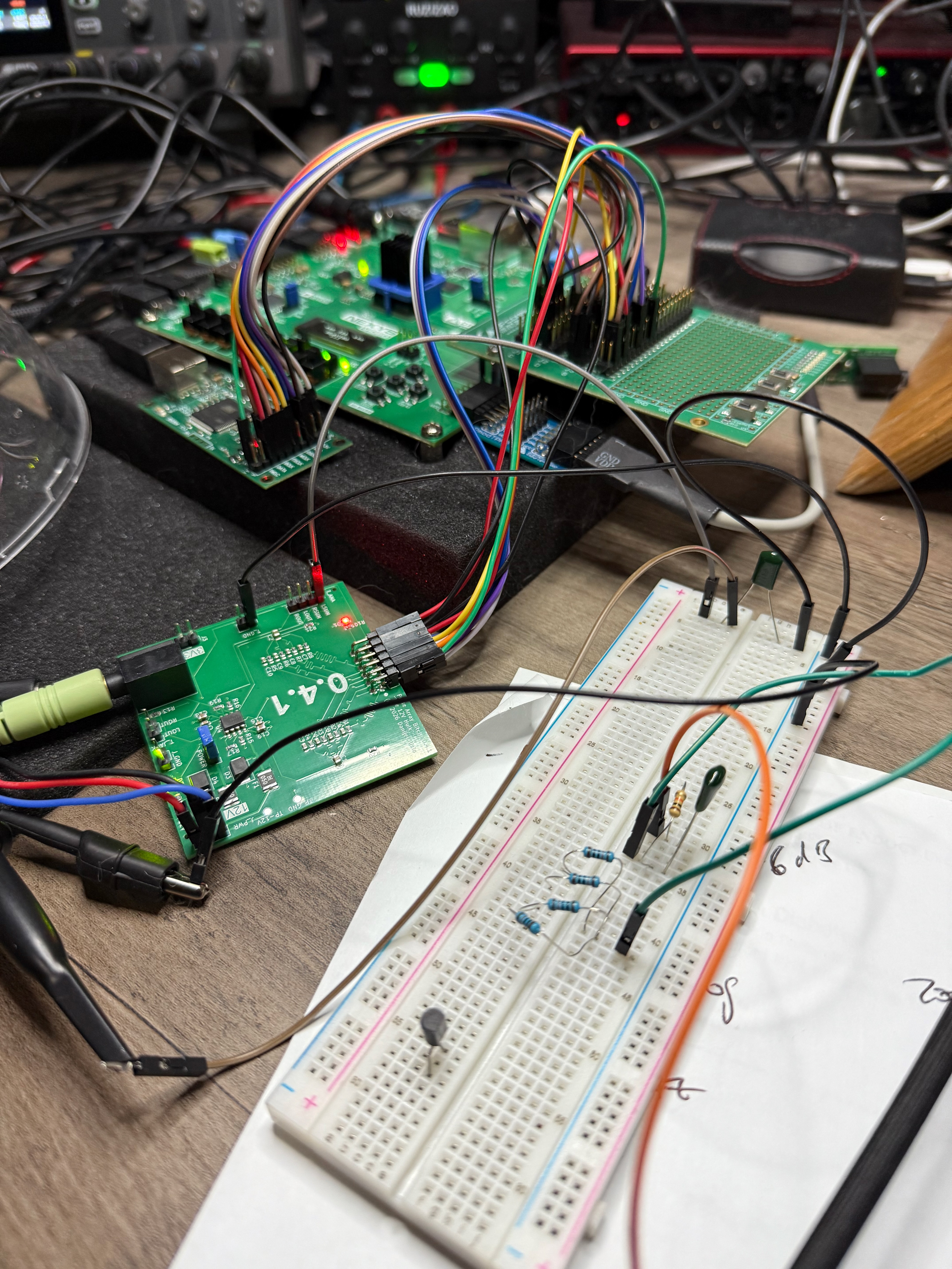
- OPA1612 opamp output stage (±12V, breadboard → custom PCB)
Signal chain:
USB Audio → Amanero I2S → FPGA →
256× Polyphase FIR (229,376 taps)
→ 5th-order CRFB SDM (65 levels)
→ Pulse Array (my own algorithm)
→ Analog Reconstruction (custom PCB, OPA1612)
→ Headphone Amplifier → Susvara
The Signal Processing — Why It Sounds Different
229,376-Tap Polyphase FIR — Transient Reconstruction
Rob Watts' core insight: above 16× oversampling, you hear "massive
changes in sound quality." Clarity, soundstage, the perception of
notes starting and stopping precisely. This is about reconstructing
transients — the sharp attacks and decays that make music feel REAL.
My implementation: 256× upsampling via polyphase FIR.
- 112 DSP tiles × 8 taps/tile × 256 phases = 229,376 coefficients
- 2 DSP48E1 blocks per tile (25×32-bit native multiply — no split)
- Zero fabric multipliers — pure DSP48 architecture
- Custom-designed sinc filter/window ("GOAT filter")
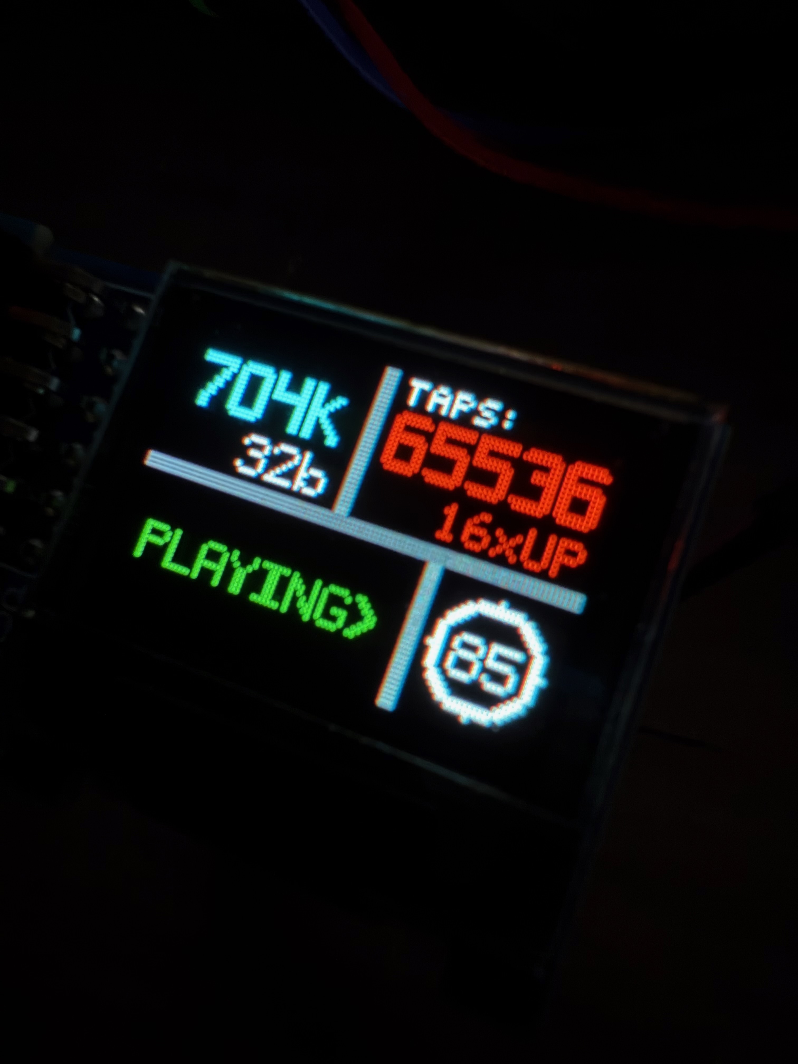
- Multi-rate output: 256×, 128×, 64×, 32×, 16× selectable
- 200MHz clock domain at 48kHz input
For context: Chord DAVE uses ~164,000 taps. I'm at 229,376.
DAVE has been passed.
The coefficients are generated in Python, uploaded via 2 Mbaud UART,
and stored in 112 parallel BRAM blocks. Each build takes ~20 minutes
on the Gaming PC (i9-14900K). Coefficient uploads take seconds.
5th-Order CRFB Sigma-Delta Modulator
The FIR outputs clean, highly oversampled audio. But you can't
feed that directly to a 1-bit or few-bit output — you need noise
shaping to push quantization noise above the audible band.

My SDM: 5th-order Cascade of Resonators, Feedback Form (CRFB).
  - 65 levels (-32 to +32 signed)
  - 1-stage DSP48 feedback pipeline (minimizes latency)
  - Noise shaped above ~100kHz (inaudible, filterable)
  - The 1-stage pipeline vs earlier 3-stage = 22dB improvement
    in noise at 100kHz. Feedback latency kills noise shapers.

The NTF coefficients are designed in MATLAB, validated against int64
golden models (~42k samples/sec), then translated to Verilog. I can
now iterate SDM designs in MATLAB before touching any hardware.
Pulse Array — Rob Watts' Invention (My Own Algorithm)
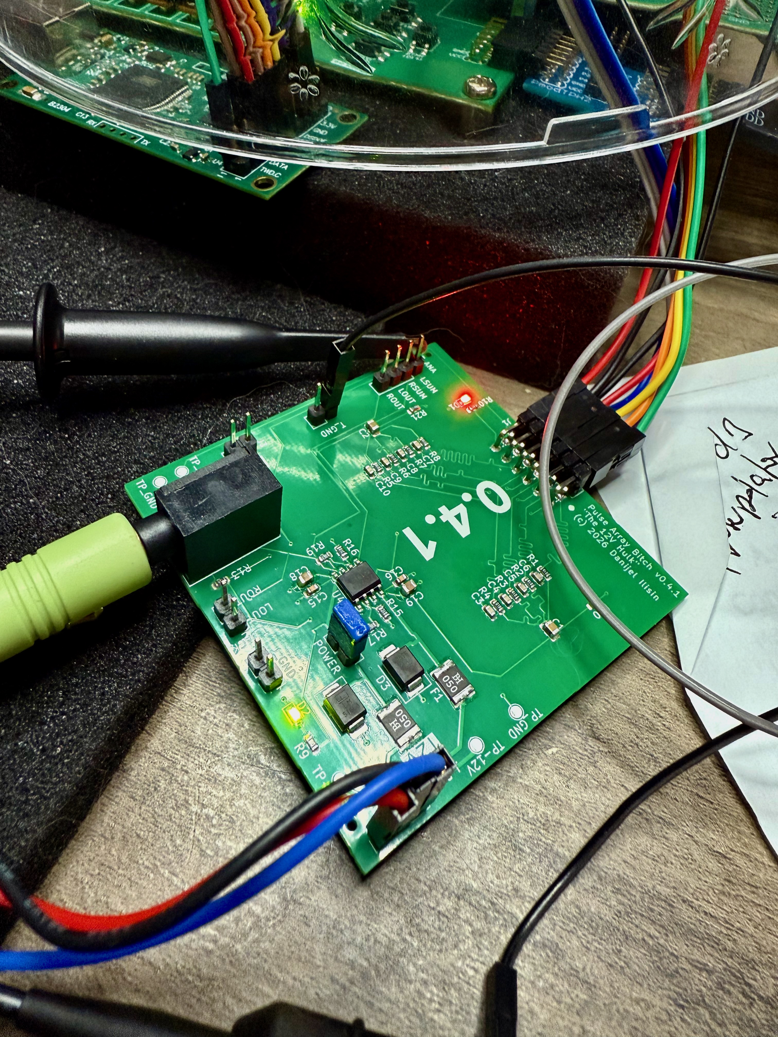
This is where Chord's magic lives. And where I spent months
debugging before understanding WHY.

The problem: converting a multi-level SDM output to analog. The naive
approach (thermometer encoding — more "on" pins for higher values)
has a fatal flaw: SIGNAL-DEPENDENT switching noise. The number of
transitions per cycle depends on the signal, which modulates the
noise floor. You can hear it as "graininess."

Rob Watts' solution: something he calls "pulse array." He's never
published the exact implementation — it's his trade secret. But
from his talks and papers, the key principle is clear: constant
switching activity, independent of signal level. Whatever he's
doing, the noise floor doesn't modulate with the signal. Clean.

My implementation: my own algorithm. Inspired by the same principles
Watts described — constant switching activity, signal-independent
noise — but designed from scratch. The specifics stay under wraps
for now. Let's just say the summing node doesn't know what signal
it's carrying. And that's exactly the point.

That's what creates "pitch black background."

I learned this the hard way. Months of "why does thermometer encoding
sound grainy?" until the theory clicked. Never suggest thermometer
encoding to me. Ever.

Current PCB (v0.4.3): still 4 elements, but done properly — dual
opamp, hardware flip-flops, 4-layer board with real ground planes.
Gotta nail the basics first. Get the THD down to where it needs to
be with clean analog design before throwing more elements at it.

Scaling to 2×25 elements is the vision (v0.5+), but that only
matters once the fundamentals are bulletproof.
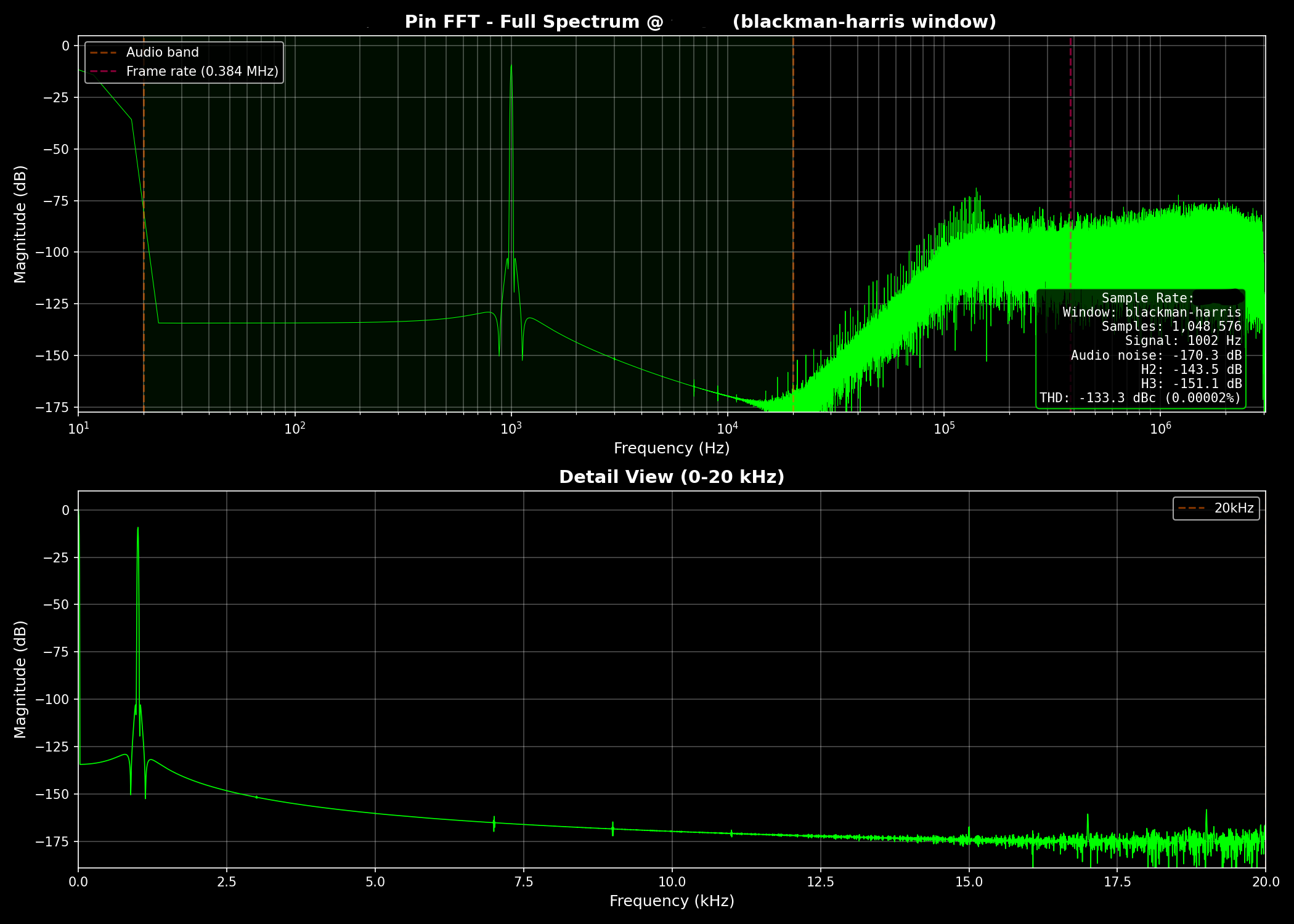
The CDC Discovery — Killing the 47kHz Horns
February 6, 2026. The day I understood clock domain crossings.

The FIR outputs samples in bursts (17.6µs of data, 3.2µs silence).
This periodic burst pattern creates intermodulation products — ugly
47kHz/49kHz sidebands at -55dB. I called them "the horns."

The fix was embarrassingly elegant: rate-limit the CDC output to one
sample every 16 clock cycles (constant rate, no bursts). Result:
the horns dropped from -55dB to -232dB. A 117dB improvement from a
one-line change.

The deeper insight: 128× upsampling at 48kHz gives an integer CDC
ratio (2048/128 = 16 cycles). Integer = clean. My earlier 72×
attempt had a ratio of 28.44 — fractional = periodic jitter =
"batman ears" in the spectrum. The math has to be CLEAN.
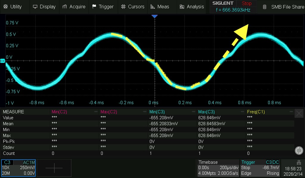
Custom PCBs — Learning Hardware From Zero
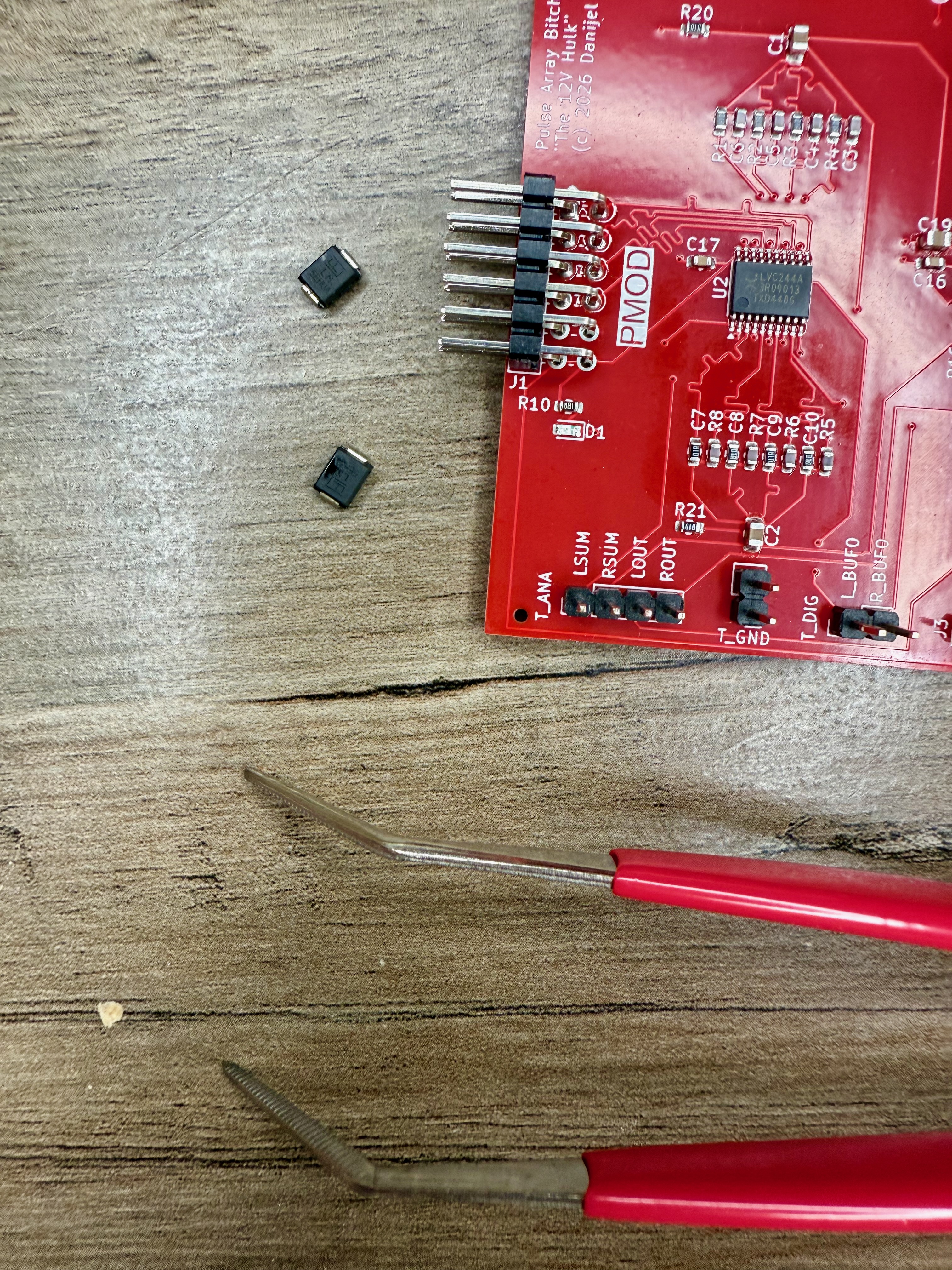
The FPGA is 50% of the project. The other 50% is getting analog
audio out of digital pulse trains. That means: opamps, resistor
networks, power supplies, ground planes, impedance matching.

Three months ago, I didn't know what KiCad was. Now I'm on PCB
revision v0.4.3 — a 4-layer custom board with:
  - Hardware flip-flops (signal integrity at FPGA output)
  - Dual OPA1612 opamp stage
  - Precision summing resistor network
  - Proper ground planes and power filtering
  - Designed for JLCPCB manufacturing

The breadboard prototype already hit -99dBc H2 (second harmonic
distortion). That's a 34dB improvement over bare FPGA pins through
a 22pF capacitor and some careful opamp configuration.

Every board revision ships from Shenzhen. I order, wait 2 weeks,
solder, test, learn, iterate. It's the slowest feedback loop in
the project — and the most satisfying when it works.

Oh, and I taught myself SMD soldering. Bought a rework station to
fix a JLCPCB assembly mistake. Three months ago I didn't know which
end of a soldering iron gets hot. Now I'm reflowing 0603 components
with a hot air gun. The speedrun has no brakes.
Screenshots — From Zero to DAC
The Hardware
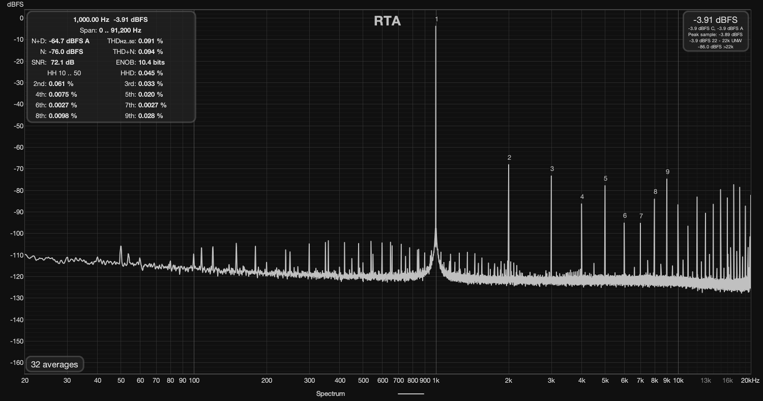
The Measurements
POST — Learnings · Afterthoughts · Timeline
What I learned:

  - You can teach yourself FPGA development from zero using AI as
    a tutor. The learning style of try → fail → ask → never forget,
    combined with Claude's patience, is absurdly effective.
    10 weeks from "what is Verilog" to a working 229k-tap DAC.

  - Rob Watts is right about tap counts. There IS a difference above
    16× oversampling. Whether it's transient precision, pre-ringing
    elimination, or something else — more taps means more real.

  - Timing violations are the norm, not the exception. This project
    has NEVER had positive worst negative slack. Not once. If it
    works on hardware, it works. Don't let the tools scare you.

  - The hardest problems are at domain boundaries. Not inside the
    FIR, not inside the SDM — at the clock domain crossings. The
    CDC rate-limiting discovery was a 117dB fix. Boundaries matter.

  - Thermometer encoding is a trap. It looks obvious. It's wrong.
    Signal-dependent switching noise is real and audible. I spent
    months learning this. Pulse array or nothing.

  - Custom PCBs from China are magical. ~$50 for a 4-layer board
    with assembly and shipping. Delivered in 2 weeks. The
    democratisation of hardware is real.

  - MATLAB is not optional for DSP work. You MUST validate
    algorithms in simulation before translating to Verilog. The
    feedback cycle is too slow otherwise.

  - The audio community is... quiet. My Head-Fi diary hasn't gotten
    much traction yet. I suspect that changes when the measurements
    hit 0.001% THD on a sub-$1000 system. Numbers talk.

The connection to everything else:
  This project is the same thing as Friend, just in a different
  domain. Friend reconstructs authentic connection from data. The
  DAC reconstructs authentic sound from samples. Both are about
  removing layers of distortion between me and reality. Both are
  about building what I need because nobody's selling it at a price
  — or quality — that makes sense.

  I've spent my life exploring what's real. If we're living in a
  simulation (and I half-believe we are), then signal reconstruction
  is literally how the universe renders experience. A DAC that
  perfectly reconstructs an analog waveform from digital samples is
  doing what reality does every time you hear a sound. Understanding
  that process — truly, at the silicon level — feels like peeking
  behind the curtain.

What's next:
  Two paths:
  1) Open-source everything — Verilog, Gerbers, BOM for JLCPCB —
     and let humanity enjoy DAVE-level audio for $500-$1000.
  2) Build a product. Present at CanJam. The Uber-DAVE: 500k+ taps,
     25+ elements per channel, -350dB theoretical noise shaping.
     Not competing with Chord — I genuinely respect their products.
     This is about pushing the limits of what's physically possible
     and seeing how far the philosophy scales.

  The measurements will speak for themselves. And if they don't —
  at least I'll have the best DAC in my living room.

Timeline (177 commits in 72 days):
  - 2025-12-15: First commit. "How hard can it be?" — famous last
    words from a man who'd never written a line of Verilog.
  - 2025-12-17: I2S deserialization working. Multi-rate detection.
    First WORKING code — tested with 44.1kHz and 96kHz audio.
    Two days from zero to receiving audio on an FPGA.
  - 2025-12 to 2026-01: FIR upsampler (64× initially). SDM
    prototypes (2nd, 3rd, 4th order — all archived). First analog
    output attempts on breadboard. Learning oscilloscopes.
    Learning what "negative slack" means (and that it's fine).
  - 2026-01: 64K-tap FIR validated against Python golden model.
    CDC input fixes. UART coefficient upload working.
    First time hearing upsampled audio through the FPGA.
    That moment. Sound coming out of something YOU built from
    nothing. From Verilog YOU wrote. Through analog stages YOU
    designed. That's the moment.
  - 2026-02-06: Rate limiting discovery. 117dB improvement.
    Integer CDC timing kills the 47kHz horns dead.
  - 2026-02-13: SDM v2 with 1-stage DSP48 feedback. 22dB better
    noise than the 3-stage version. Feedback latency matters.
  - 2026-02-15: Pulse array output stage — my own algorithm.
    Inspired by Rob Watts' philosophy, implemented my own way.
  - 2026-02-16: Doubled to 128× FIR. 56 tiles × 128 phases.
    114,688 taps. Closing in on DAVE's ~164k.
  - 2026-02-20: HDMI 720p video output with real-time FFT spectrum.
    OLED display via Digilent PMOD. Because why not.
    A/B testing via hardware switch.
  - 2026-02-23: HDMI + DAVE regime analysis.
  - 2026-02: 256× FIR. 112 tiles × 256 phases. 229,376 taps.
    25×32-bit native multiply — 2 DSPs per tile instead of 4.
    Custom-designed sinc filter/window — the "GOAT filter."
    DAVE's ~164k taps: passed.
    Still going. Still learning. Still chasing perfect sound.

Current state:
  - PCB v0.4.3 from JLCPCB (4-layer, 4 elements, dual opamp,
    hardware flip-flops — nailing the analog fundamentals)
  - MATLAB workflow integrated for SDM coefficient iteration
  - Head-Fi diary active, diyaudio thread started
  - Next milestone: get THD down with clean analog design
  - Future: scale to 2×25 elements (v0.5+) once basics are solid
  - The question I can't answer yet: how does it SOUND?